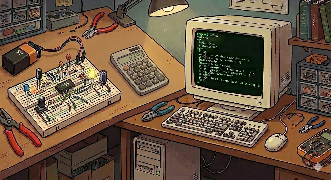
A Story from an Automation Technician Link to heading
In 2010 I graduated as an Industrial Automation technician. If you are not sure what that means, think of factories, conveyor belts, robots, PLCs, sensors and a pile of acronyms most people will never need to know. It was an amazing course, mixing electronics, mechanics and, this is where the story begins, programming.
That was more or less when I started programming for real. And the first language I learned was Pascal.
Pascal is a language you will rarely find being taught in new courses these days, but for many years it was the standard language for teaching programming logic. It is verbose, structured and quite readable, perfect for someone who is learning.
After the coursework exercises, I started thinking: what if I built something useful? Something I could actually use day to day in the course? That is how my first real program was born: a calculator for the 555 integrated circuit.
What Is the 555 Integrated Circuit? Link to heading
If you have never heard of the 555 IC, know that it is an electronics legend. Released in 1972 by Signetics, this tiny 8-pin chip is considered one of the best-selling electronic components of all time. Estimates say billions of units have been manufactured.
The 555 is a timer. With it, you can generate electrical pulses, control timings, blink LEDs, trigger alarms and do dozens of other practical things with very few external components: basically resistors and capacitors.
A resistor is a component that limits the flow of electrical current. Think of it as a rock in the middle of a river, the bigger the rock, the less water gets through. A capacitor is a component that stores electrical energy temporarily, like a small reservoir that fills up and empties out.
Here is what it looks like in a diagram:
                    ||= = = = = = =||
                 ---||7      8   4 ||---
                    ||             ||
                 ---||6            ||
                    ||    555    3 ||---
                    ||             ||
                 ---||2          5 ||---
                    ||      1      ||
                    ||= = = = = = =||
Each number represents one of the chip’s 8 pins, each with a specific function:
| Pin | Name | Function |
|---|---|---|
| 1 | GND | Ground (electrical reference, 0V) |
| 2 | Trigger | Starts the timer |
| 3 | Output | Where you connect whatever you want to control |
| 4 | Reset | Resets the chip |
| 5 | Control Voltage | Control voltage |
| 6 | Threshold | Defines when the capacitor is “full” |
| 7 | Discharge | Capacitor discharge |
| 8 | VCC | Positive supply |
The 555 can operate in two main modes: astable and monostable. That is exactly what my program calculated.
Astable Mode: The Eternal Oscillator Link to heading
In astable mode, the 555 keeps oscillating on its own, generating an electrical wave that alternates between on and off without stopping, like an electronic heart that beats by itself.
That is useful for blinking an LED, generating a continuous sound, driving a motor at intervals, and so on.
The circuit looks like this:
                       ↑ VCC
             RA        |
           /\/\/\------|__ _ __ _ _
          |            |          |
          |   ||= = = = = = =||   |
          /---||7      8   4 ||---|
      RB  \   ||             ||
          /   ||             ||
          \---||6    555    3||---OUTPUT
          |   ||             ||
          |---||2          5 ||---|
          |   ||      1      ||   |
        __|__ ||= = = = = = =|| __|__
        _____ C1       |        _____
          |            |          | 10
          |____________|__________| nf
                     __|__
                      ___ GND
                       _
In this circuit, RA and RB are resistors and C1 is the capacitor. How it works is easy to follow:
- The capacitor C1 starts charging from the current flowing through both resistors (RA and RB).
- Once it is charged enough, the 555 switches the output from high to low and starts discharging the capacitor, but now only through RB.
- Once it is discharged enough, the process starts over.
That endless cycle generates a square wave at the output. The formulas for calculating the characteristics of that wave are:
Frequency  (Hz) = 1.44 / ((RA + 2×RB) × C)
High time   (s) = 0.693 × (RA + RB) × C
Low time    (s) = 0.693 × RB × C
Period      (s) = High time + Low time
Frequency is how many times per second the cycle repeats. Period is the duration of one complete cycle. They are inversely proportional: the higher the frequency, the shorter the period.
Monostable Mode: The Single Pulse Link to heading
In monostable mode, the 555 sits quietly waiting for an external trigger. When it receives that signal (usually a pressed button or another circuit), it generates a single pulse of a given duration and then goes back to rest.
It is useful for creating timings: “turn this lamp on for exactly 10 seconds”, “lock that door for 5 seconds”, and so on.
The circuit looks like this:
                       ↑ VCC
              R        |
           /\/\/\------|__ _ __ _ _
           |           |           |
           |  ||= = = = = = =||    |
           ---||7      8   4 ||----|
           |  ||             ||
           |  ||             ||
           |--||6    555    3||---OUTPUT
           |  ||             ||
  Trigger--)--||2          5 ||---|
           |  ||      1      ||   |
           |  ||= = = = = = =|| __|__
         __|__         |         _____
       C _____         |          | 10
           |___________|__________| nf
                     __|__
                      ___ GND
                       _
Here we only need one resistor R and one capacitor C. The timing formula is simple:
Timing (s) = 1.1 × R × C
You just pick the values of R and C to get the time you want.
The Pascal Program Link to heading
With those concepts in mind, I wrote my first program. The idea was: the user enters the component values (resistors and capacitor) and the program computes the results and draws the circuit on screen.
All of that in Pascal, straight in the terminal. No graphical interface, no mouse. 😄
You can try the code online at: https://onlinegdb.com/9Lpl7RIFN
The program starts with a main menu showing the 555 symbol drawn in ASCII art. The original code is in Portuguese, exactly as I wrote it back then:
program prog555;
uses crt;
var
  opcao: String;

begin
  opcao := '0';
  while opcao <> '3' do
  begin
    clrscr;
    writeln('Progama para calculos do multivibrador 555    Versão 3.0');
    writeln('Bem vindo ao menu de opções escolha sua opção:');
    writeln('                            ||= = = = = = =||       ');
    writeln('                         ---||7      8   4 ||---    ');
    writeln('                            ||             ||       ');
    writeln('                         ---||6            ||       ');
    writeln('                            ||    555    3 ||---    ');
    writeln('                            ||             ||       ');
    writeln('                         ---||2          5 ||---    ');
    writeln('                            ||      1      ||       ');
    writeln('                            ||= = = = = = =||       ');
    writeln('1-Modo Astável, 2-Modo Monoestável, 3-fim do programa');
    readln(opcao);
    CASE opcao OF
      '1': modoastavel;
      '2': modomono;
      '3': break;
    else
      writeln('Numero invalido');
      delay(500);
    END;
  end;
end.
The astable mode calculation looked like this, notice the formulas sitting right inside the writeln:
procedure modoastavel;
var
  ra, rb, c1, i: real;
  op: string;
begin
  // reading the values of RA, RB and C1...
  if (ra >= 1) and (rb >= 1) and (ra <= 10000) and (rb <= 10000) then
  begin
    writeln('Frequência é:', 1.44 / ((ra + (2 * rb)) * c1):5:2, ' Khz');
    writeln('Tempo em nível alto do pulso', (0.693 * ((ra + rb) * c1)):5:2, 'ms');
    writeln('Tempo em nivel baixo do pulso', (0.693 * rb * c1):5:2, 'ms');
    writeln('Periodo é:', ((0.693 * ((ra + rb) * c1)) + (0.693 * rb * c1)):5:2);
  end;
end;
And the monostable mode:
procedure modomono;
var
  r, c, cont: real;
  op: char;
begin
  // reading the values of R and C...
  writeln('Temporização é:', (1.1 * r * c):5:2, 'segundos');
end;
Simple, straight to the point. The formulas applied there are exactly the ones we saw in the previous sections. Back then, watching the computer calculate a result I would otherwise have to work out by hand (or on a calculator) was an incredible feeling.
The complete code is available at: github.com/cassiobotaro/meu_primeiro_programa/blob/master/meuprog.pas
Years Later: Rewriting It in Python Link to heading
Some time later, already more experienced and programming in Python, I decided to rewrite the same program. I admit the intention was almost a faithful transcription of the Pascal, I did not want to change the logic, only adapt it to Python syntax.
Here is how the menu turned out in Python:
def main():
    opcao = 0
    while opcao != '3':
        opcao = input(
            '''
    Programa para cálculos do multivibrador 555

    Bem vindo ao menu de opções escolha sua opção:

                             |
                             |
                    ||= = = = = = =||
                 ---||7      8   4 ||---
                    ||             ||
                 ---||6            ||
                    ||    555    3 ||---
                    ||             ||
                 ---||2          5 ||---
                    ||      1      ||
                    ||= = = = = = =||
                            |
                            |

    1-Modo Astável, 2-Modo Monoestável, 3-fim do programa
            '''
        )
        if opcao == '1':
            modoastavel()
        elif opcao == '2':
            modomono()
        elif opcao == '3':
            print("Até mais! =)")
        else:
            print("Opção inválida")
            sleep(.5)
And the astable mode calculation in Python, now with more descriptive variable names:
def modoastavel():
    capacitor = float(input('Digite o valor do capacitor(uF): '))
    resistor_a = float(input('Digite o valor de RA(k ohms): '))
    resistor_b = float(input('Digite o valor de RB(k ohms): '))

    frequencia = 1.44 / ((resistor_a + 2 * resistor_b) * capacitor)
    frequencia *= 1000  # converts to hertz

    nivel_alto = 0.693 * ((resistor_a + resistor_b) * capacitor)
    nivel_baixo = 0.693 * resistor_b * capacitor

    if (1 <= resistor_a <= 10000) and (1 <= resistor_b <= 10000):
        print(f'Frequência é: {frequencia:.3f} hz')
        print(f'Tempo em nível alto do pulso: {nivel_alto:.3f} ms')
        print(f'Tempo em nível baixo do pulso: {nivel_baixo:.3f} ms')
And the monostable mode:
def modomono():
    resistor = float(input('Digite o valor de R(K ohms): '))
    capacitor = float(input('Digite o valor do capacitor(uF): '))

    temporizacao = 1.1 * resistor * capacitor
    print(f'Temporização é: {temporizacao:.3f} ms.')
The logic is identical. The difference is in the syntax: Pascal is more verbose (with begin, end, writeln, readln), while Python is more concise and readable.
The complete Python code is at: github.com/cassiobotaro/meu_primeiro_programa/blob/master/meuprog.py
Final Reflection Link to heading
Looking at that code today, it is impossible not to smile. It was a simple program, full of imperfections: one-letter variable names, basic validation, no error handling. But it was my program, built to solve a real problem from my course.
That is the most important point: it does not matter whether the code is perfect. What matters is that it solves something, that you learn by doing, and that every program leaves you a little better than you were before.
If you are just starting out, do not wait until you have mastered the language to start creating. Pick a small problem that is real to you, and solve it. Even if the code turns out ugly, the learning will be enormous.
That’s it, folks!
See you next time!
{}’s